|
Now that I have JAMMA Capabilities in my cabinet, my
control panel has two different things to connect to. The Computer
(gamepads), and the JAMMA (original arcade games) boards that I own.
The problem is this, now that I have two things to control with the
control panel, I need a way to switch between them. My original
solution was to use male and female 25pin (serial type) connectors that I
could manually just connect and disconnect when I needed to switch between
the computer and JAMMA boards. You can see this layout on the JAMMA
page. I wanted an easier way to do this. I
knew the solution would lie in building some type of circuit switch to do it
in a small package, but having never built any type of circuit ever, I had
no idea where to begin. Well, let me rephrase that. I have never
built a real circuit with my hands. I have taken circuits, and various
types of electronics classes in school, but none had any real hands on
experience. Most of the work was done in CAD programs and such.
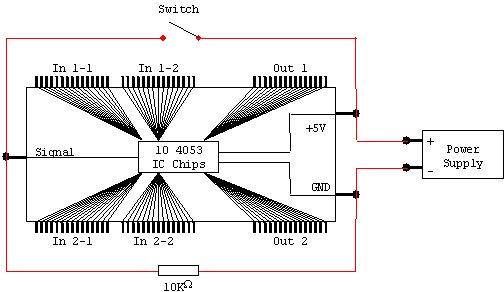
I began to search the net and found people who have built circuits for keyboard, and joystick switches. I was on the right track, but most of those designs were too complicated for what I needed and I still couldn't tell what was doing the actual "switching". Then finally I found some references to CMOS chips. These are small Integrated Circuits, most of which have a few simple gates built in for people who like to tinker with electronics. I found one that had 3 2-to-1 multiplexors built into it, number 4053. Basically a multiplexor, in case you don't know, is a switch that has multiple inputs that can be switched to a single output. The 2-to-1 type has two inputs and one output which is exactly what I needed! So counting all of the switches for both players on my control panel, I figured I needed to be able to switch 30 wires. Since there are three of those multiplexors on each chip, I needed a total of 10 chips to switch everything I needed (at a whopping .50 cents a piece from Radio Shack) By the way, when ordering these things make sure NOT to get the "surface mount" types. They are much smaller and are nearly useless to the casual hobbyist like me. Here's a picture of my preliminary design for the circuit. Later, I was advised to exchange places with the switch and the resistor so I did that in the final circuit.
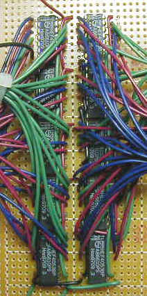
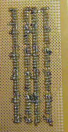
While I waited for my chips to arrive in the mail, I went to a local Radio Shack and bought a mini PCB board to assemble the circuit with. When they arrived a couple of days later, I anxiously took one of the extra chips (I bought 5 extra just in case) and assembled a quick and dirty test to a power supply to see if they worked the way I had hoped, and they worked great. I immediately began assembling the circuit as I had planned, and soldered them all to the PCB board (I'm getting really good at soldering now.) I connected the whole circuit together and plugged it into the +5V power supply I had planned on using, and everything worked great except I was getting a really weird behavior. The multiplexors were behaving with an intermittent pattern. When I checked the continuity with a meter it would pulse on and off with approximately a second interval. The only reason I could think of was because I'm using 10 chips, the circuit is drawing more power than +5V can handle, so I used a +12 volt power supply instead and the pulse went away. The connection is nice and solid now. If anyone out there has a better explanation as to why this happened please let me know. Here are a couple of pictures of the finished circuit: Component side and the "I'm surprised it works" solder side
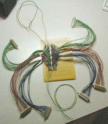
The Whole Circuit from above with connectors
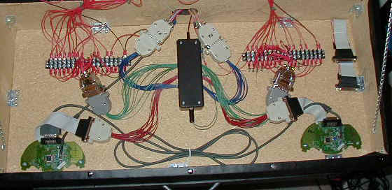
To my amazement it all worked pretty much first try. The only hang-up was with the diagram I got on the net for the pin layout on the chips was different from the chips I got, but it was a minor difference and was easy to fix. In this picture the green connectors are the outputs and the red and blue connectors are the inputs. The two wires up top are the power and ground, and the two green wires on the bottom are the actual switch. The great thing about this setup is I don't have to change anything inside the control panel at all. Everything will plug into the existing connectors I already have in the control panel for all of the buttons, gamepads, and JAMMA boards. To make it nice and neat I went to Radio Shack again and bought a small project box, and cut the PCB to fit inside it. I also added male/female connectors for the power and the switch to make it easy to disconnect them if I ever need to remove the box from the control panel. Here's a shot of the box installed in the Control Panel
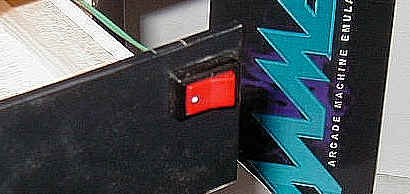
In this picture you can see the green connectors (outputs) are hooked up to the control panel buttons, the Red Connectors (inputs 1) are hooked up to the MS Gamepads, and the Blue Connectors (inputs 2) are hooked up to the JAMMA Connectors. I installed a rocker switch on the keyboard drawer for the switch.
Now I can switch control to the Computer or Arcade boards with the flip of a switch! Awesome! |